EPB-Endurance Test rig
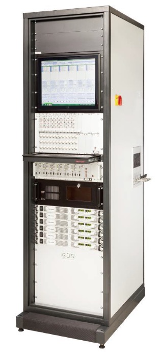
The test stand is designed for the endurance test of 12 electrical parking brakes (EPB).
The brakes are electrically controlled in pairs of 6 modules working independently of one another. Operation takes place via the modules or via an external control device.
The definition and transfer of the test program is carried out via PC Windows’s software.
Three separate hydraulic units enable the hydraulic control of three pairs of brakes.
Hardware
The hardware is contained in a 19" cabinet:
Front view:
- 19" screen to view the operating software / program status
- 6RU - placeholder for integrating measurement
instrumentation/signal conditioning
- Rack with 6 control modules and status display
- Keyboard slot with mouse repository
- 6 power supply units at 20V / 60A
- PC for operation and module communication
Internal:
- Cabinet ventilator with thermostat
- Switch for ethernet connection
- dSPACE- PC for CAN- Simulation
- Distributors with automatic circuit breakers
- Electrical brake connections
- 3 hydraulic units with brake fluid reservoirs, proportional valves,
pressure sensors and bleed pump
Left-hand side:
- Pneumatic supply
- Hydraulic circuit 1/3/5
- Connection recess
Right-hand side:
- Electrical mains switch
- Electrical supply
- De-aeration pump switch
- Warning lamp "re-fill brake fluid reservoir"
- Hydraulic circuit 1/3/5
- Connection recess
Operating Software EPB- Tester
It functions as the interface between user and control modules. It can be used to operate the brakes/ ECUs both manually and automatically by creating and transmitting endurance programs.
Similarly, the user can retrieve information about the current status of the program and view the values of the individual cycles via Plotter features.
The operator software includes different interfaces:
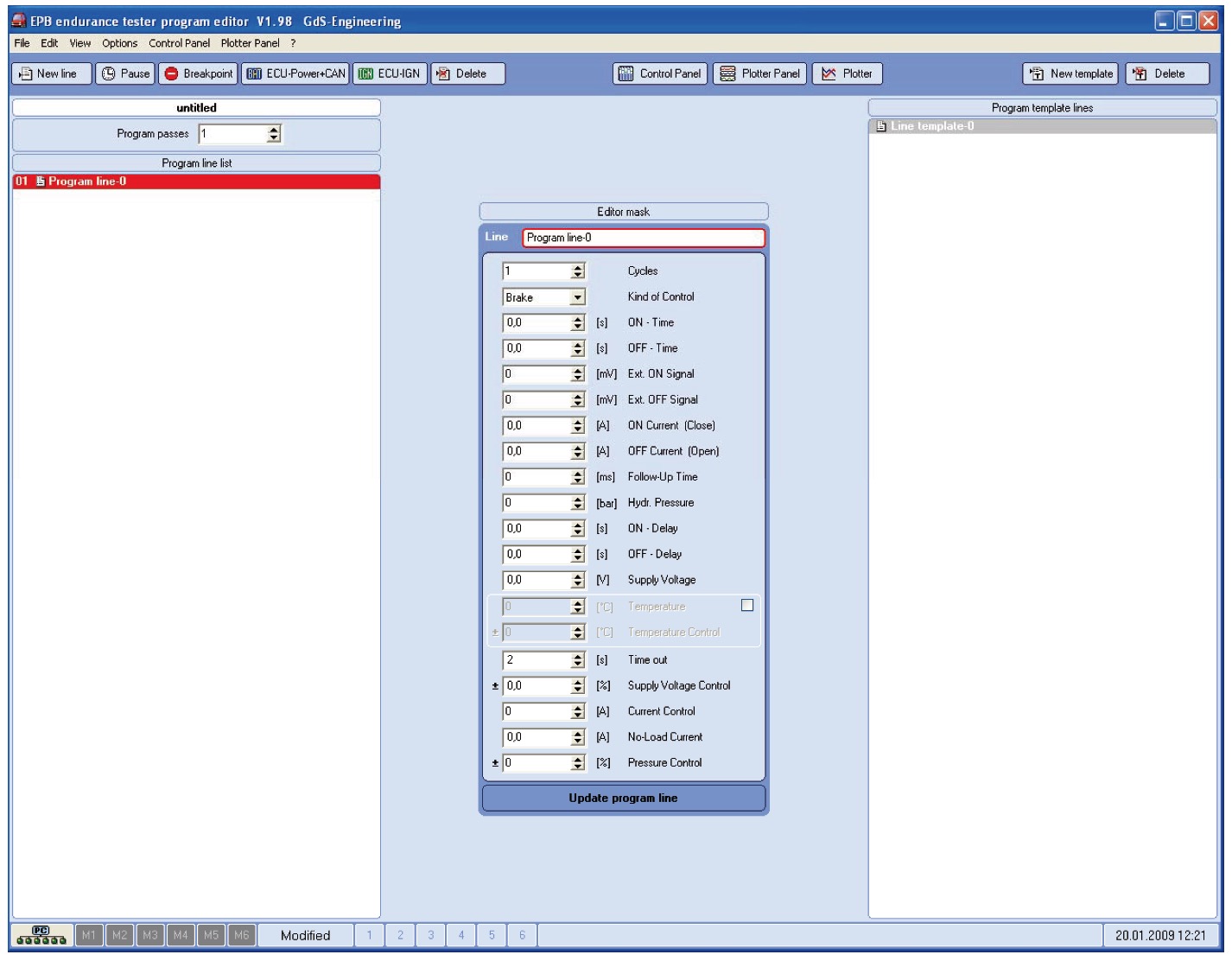
1、Editor
The editor contains all functions which are necessary to create a test program and to send it to the control modules.
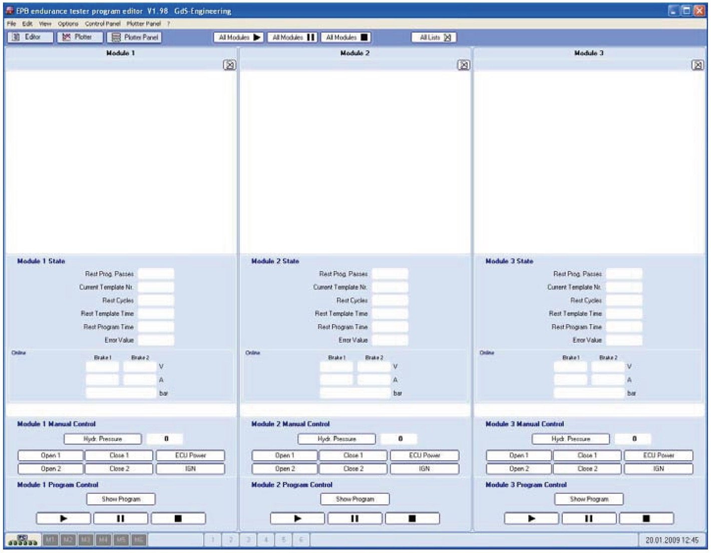
2、Control Panel
The Control Panel enables the user to control the modules and to get an overview about the program status. A running test program can be controlled, and the user can actuate manually the brake and the hydraulic actuation.
3、Plotter- Panel
The multi plotter control allows a total view about the electrical and hydraulic actuation of all active modules. On the right side of the plotter the momentary numerical values can be read.The measuring data in the plotter are updated with a frequency of 100 hertz.
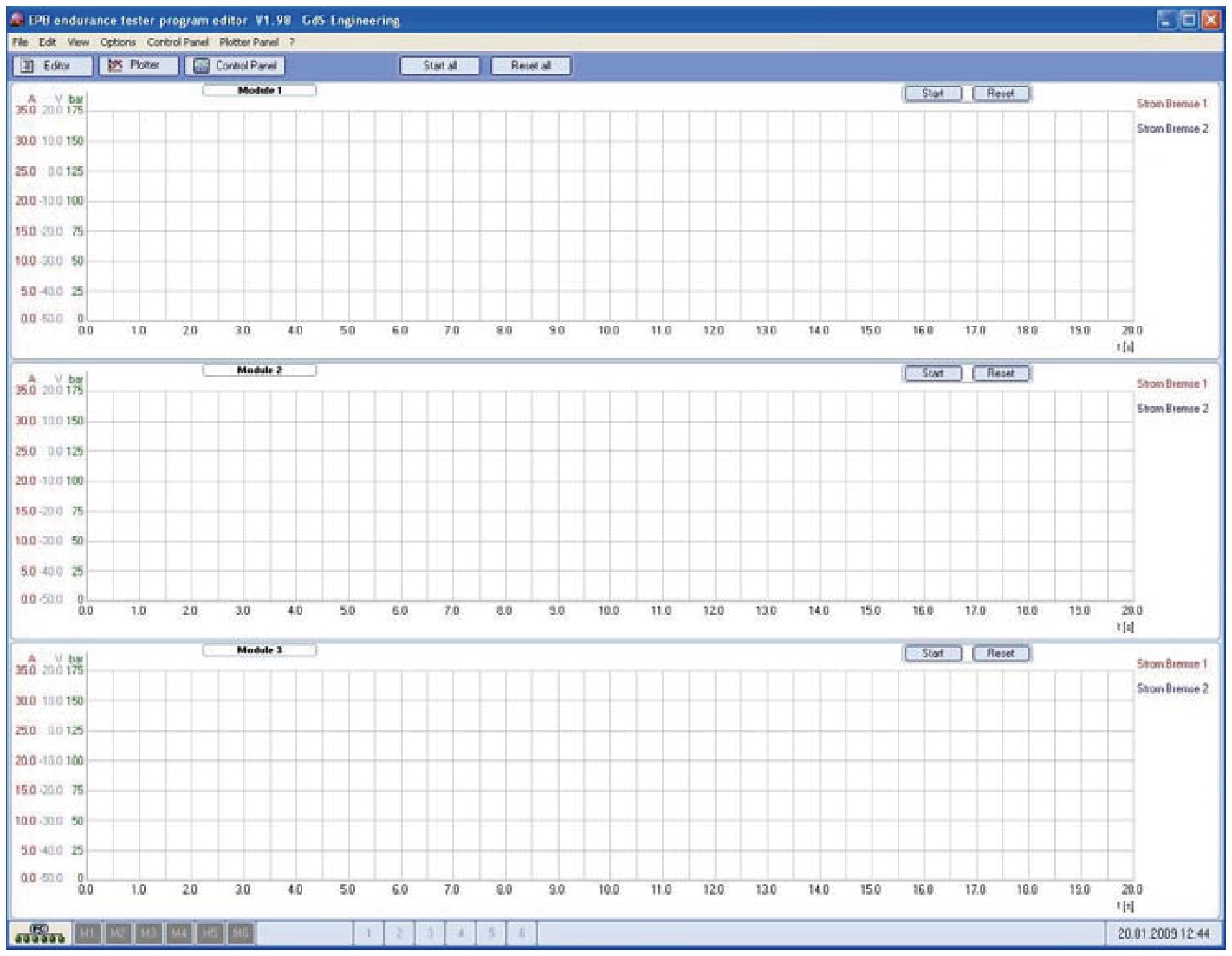
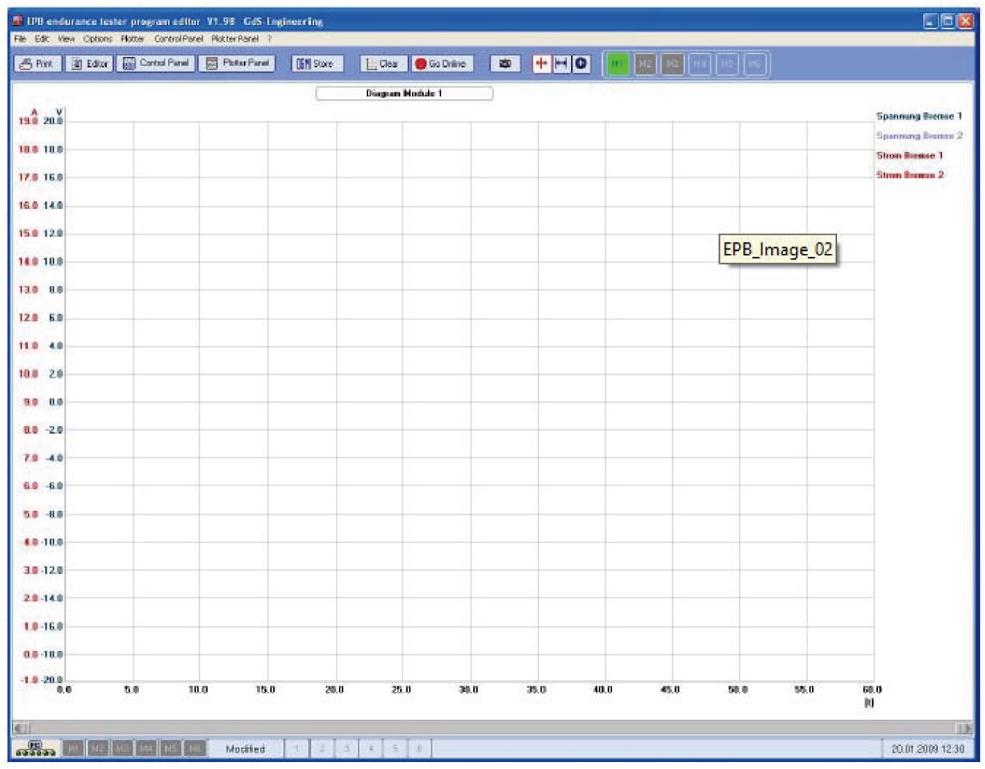
4、Plotter
The (single-) plotter gives exact information’s about momentary values.
So e.g. an interim change of the No- load current can be controlled at
