Technical solution for RT two car ADAS testing system
System Overview
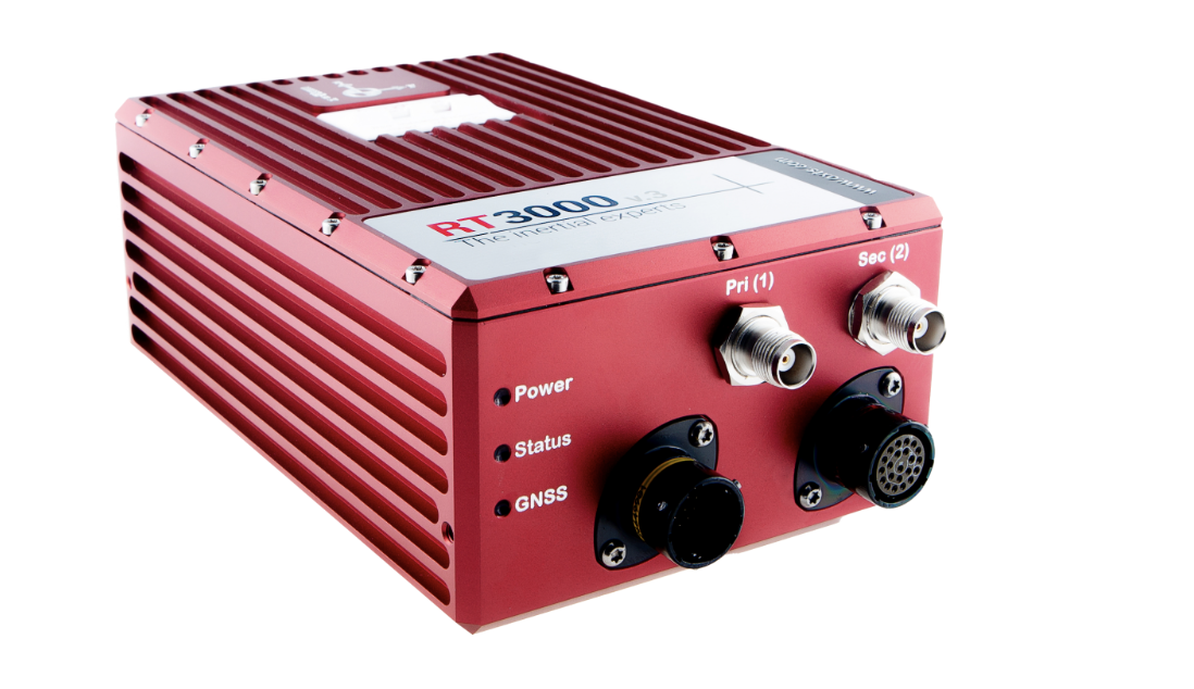
Target verification in compliance with global NCAP standards
RT Range-S extends our precise and reliable single vehicle dynamic measurement by handling the distance, direction, and relative motion of multiple vehicles. RT Range is used globally for target verification of cameras, radars, and LiDAR sensors, as well as intelligent connected vehicle testing of braking, lane departure warning, and collision prevention systems.
Measurement between vehicles and targets, as well as lane position measurement
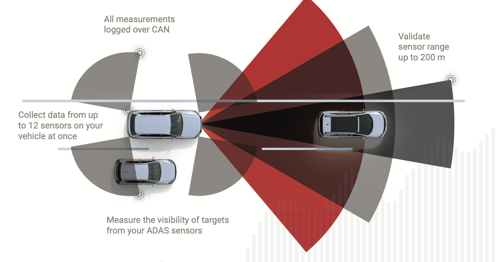
RT Range can be used to accurately measure the relative motion and distance between up to four target vehicles and the test vehicle (VuT) or Hunter vehicle. Calculate the measurement data between vehicles at a distance of over 1 km. The system can also accurately measure the position relative to lane markings, as well as up to 60000 surveying feature points, such as traffic signals. Real time display of measurement data and output through CAN in Hunter vehicles.
Simultaneously measuring the distance to four targets
RT Range can establish a real-time network that can track up to four targets and calculate distance, collision time, and other related measurement data in real-time. The target can be a vehicle, soft target, pedestrian model, or nearby objects.
Measure the visibility of the nearest point and target
Draw the contours of the Hunter and target vehicle to create a polygon with up to 24 points. RT Range S can automatically calculate distance measurement data and target visibility between the nearest polygon points, and these features are designed to support testing of parking assistance systems and collision prevention systems.
Intelligent connected road testing
Received DGPS correction through NTRIP for testing on public roads.
Testing between vehicles and pedestrians
Use RT Backpack accessories for the complete turnkey target system inside backpacks carried by pedestrians. Can track the position of pedestrians relative to moving vehicles.
CAN bus data
The RT Range S system has real-time CAN display and recording functions. Multiple vehicle CAN data can be recorded to a file within a few seconds.
Application
Euro NCAP's urban and intercity AEB
Euro NCAP's AEB VRU for cyclists and pedestrians
• NHTSA's FCW 1, 2, 3
Lane Departure Warning (LDW)
Blind spot detection (BSD)
Adaptive Cruise Control (ACC)
• Rear Intersection Traffic Warning System (RCTA)
Parking assist system and reverse assist system
Intelligent headlight verification
• Traffic sign recognition
Road intelligent networking function test
Intelligent networking function test for driving robots
Technical parameters:
| Parameter | Condition | Specifications |
| Side distance to lane | ±30m | 0.02m |
| Side speed to lane | ±20m/s | 0.02m/s |
| Lateral acceleration to lane | ±30m | 0.1m/s² |
| Longitudinal range | ±200m | 0.03m |
| Side range | ±200m | 0.03m |
| Result range | 200m | 0.03m |
| Longitudinal range speed | ±50m/s | 0.02m/s |
| Side range velocity | ±20m/s | 0.02m/s |
| Result Range Speed | ±50m/s | 0.02m/s |
| Result yaw angle | 360° | 0.1° |
Technical characteristics
Real time V2V and V2X measurements
The distance between Hunter and the target can reach up to 1 km
Measure the visibility of the nearest point and target
• Vehicle lane measurement
Real time bird's-eye view of the testing area
CAN interface
Driving robot interface
Surveying up to 60000 road assets
Testing System Architecture
The system connection is very simple. When conducting V2V intelligent driving tests, the front and rear vehicles achieve motion control and parameter collection through the RT Range system, and the two vehicles are connected in real-time through wireless communication. So as to achieve the intelligent networking function testing required by various regulations. By using a high-precision RT base station, achieve 2CM positioning accuracy for two vehicles.
Equipment to be configured for the main vehicle (Hunter):
1) RT 3000V3 high-precision gyroscope
2) RT Range S Hunter operation box (already built-in in RT3000V3, becoming a software option)
3) RT XLAN Hunter wireless receiving/transmitting module
4) J3 Radio, gyroscope and RT base station communication module
5) RT Strut is used to install the bracket for RT3002
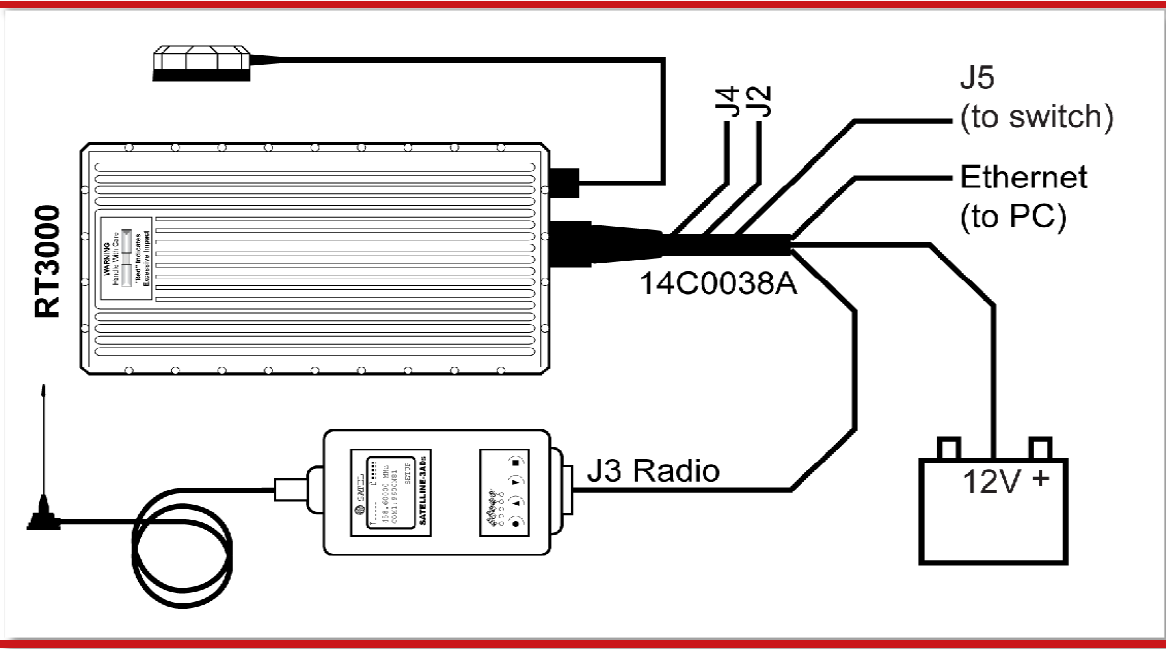
Main Vehicle System Connection Diagram
Equipment that needs to be configured for the target vehicle
1) RT 3000V3 high-precision gyroscope
2) RT Range S Target operation box (built-in with RT3000V3, becoming a software option)
3) RT XLAN Target wireless receiving/transmitting module
4) J3 Radio, gyroscope and RT base station communication module
5) RT Strut is used to install the bracket for RT3002
The target vehicle system wiring diagram is as follows:
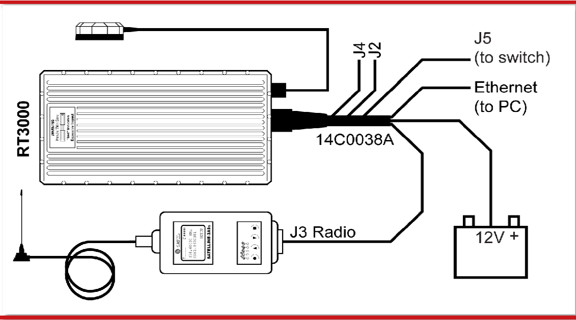
Target vehicle system wiring diagram
RTK base station (RT Base) configuration: (Network RTK can also be used)
The testing ground provides real-time differential RTK signals to achieve precise positioning of the target vehicle and the main vehicle within ± 2cm.
1) RTK base station
2) Mushroom head antenna
3) Lane line survey vehicle
4) Digital radio station
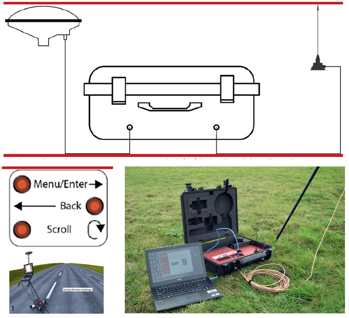
Architecture of RT base station and survey vehicle equipment